Determination of the right-angle gear
SERIES IDENTIFICATION
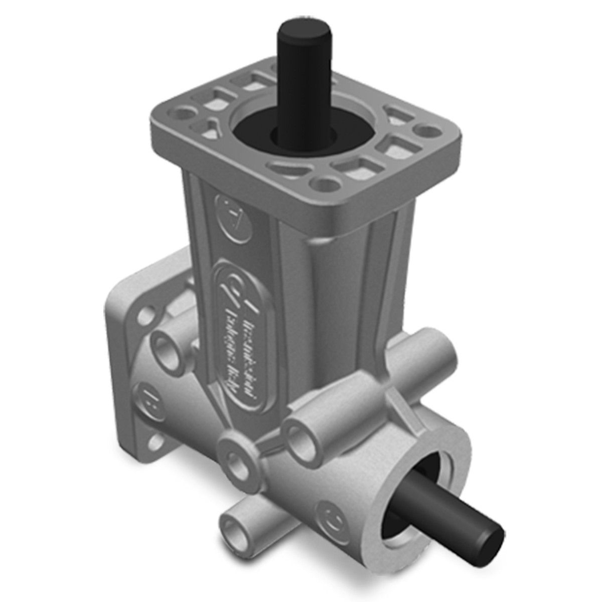
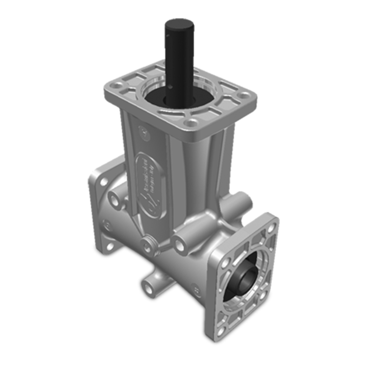
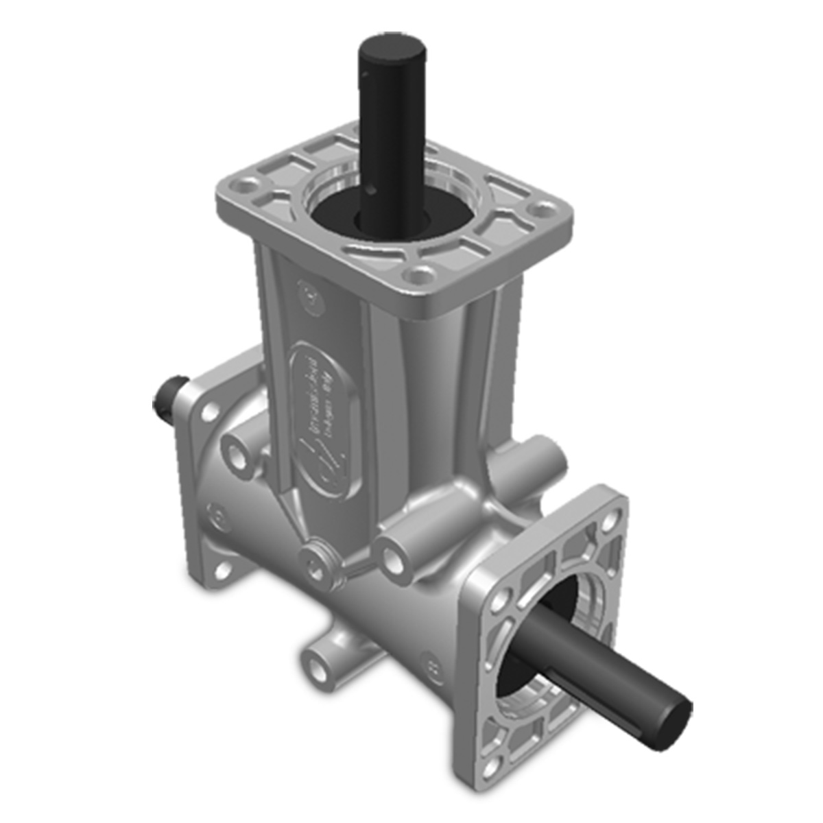
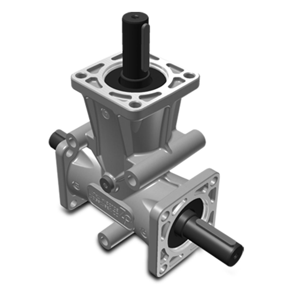
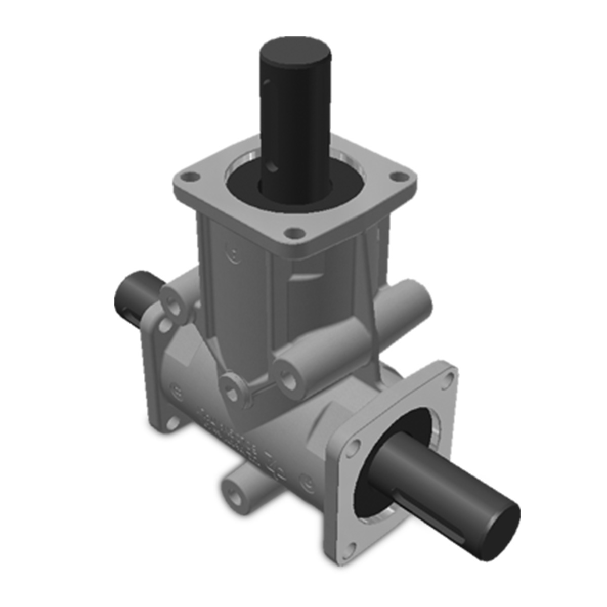
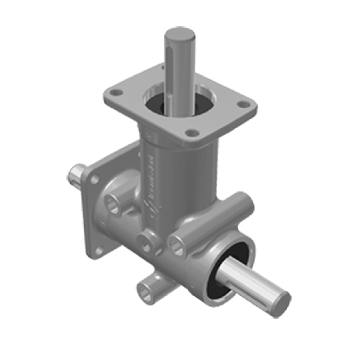
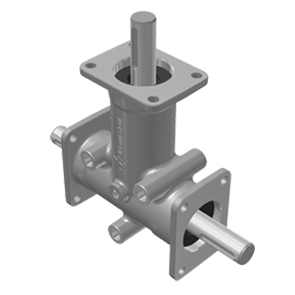
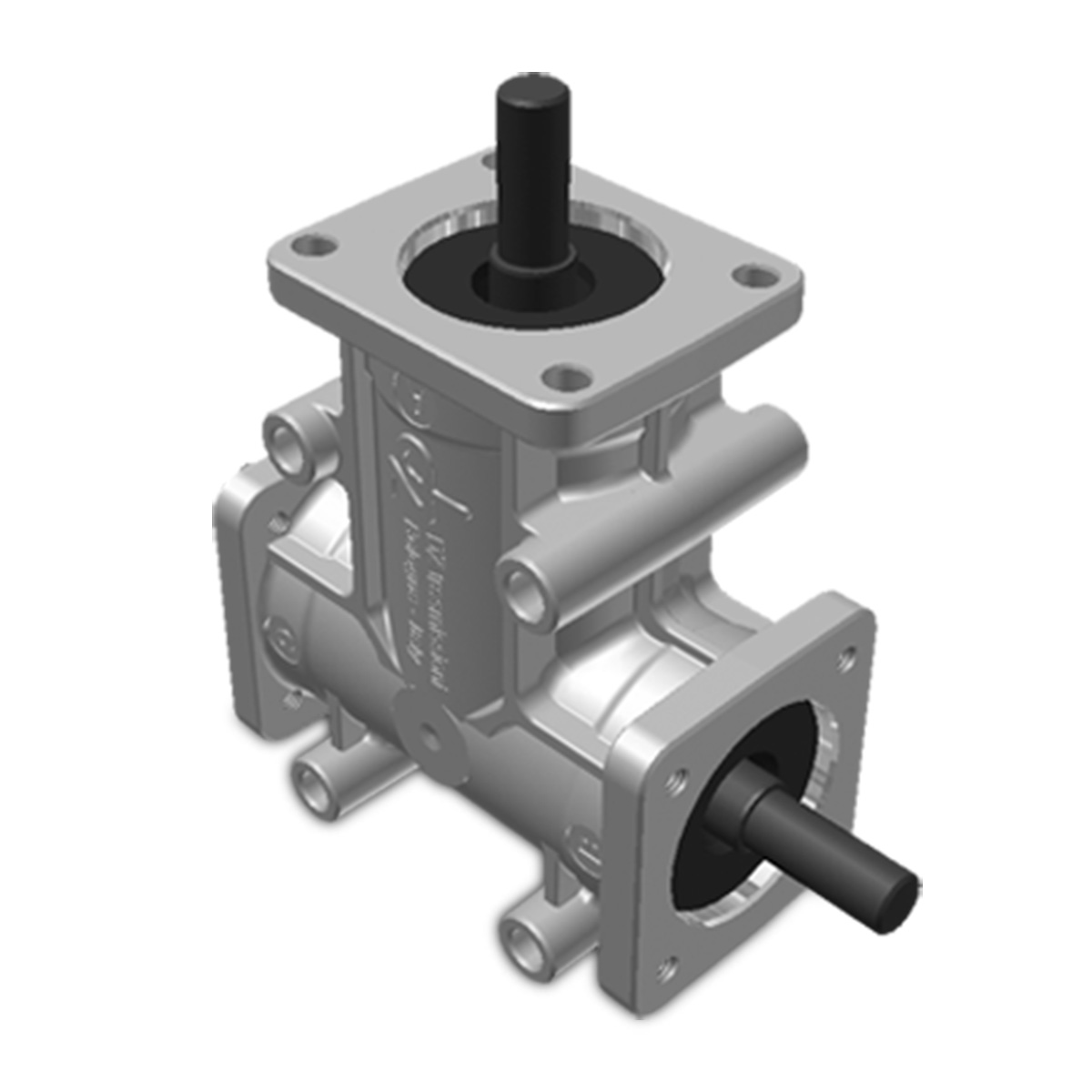
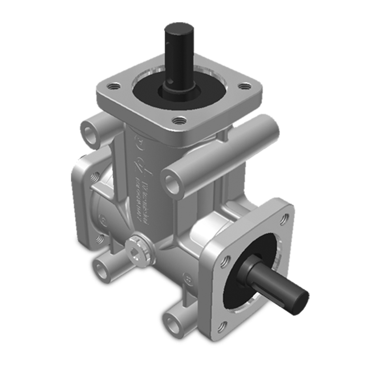
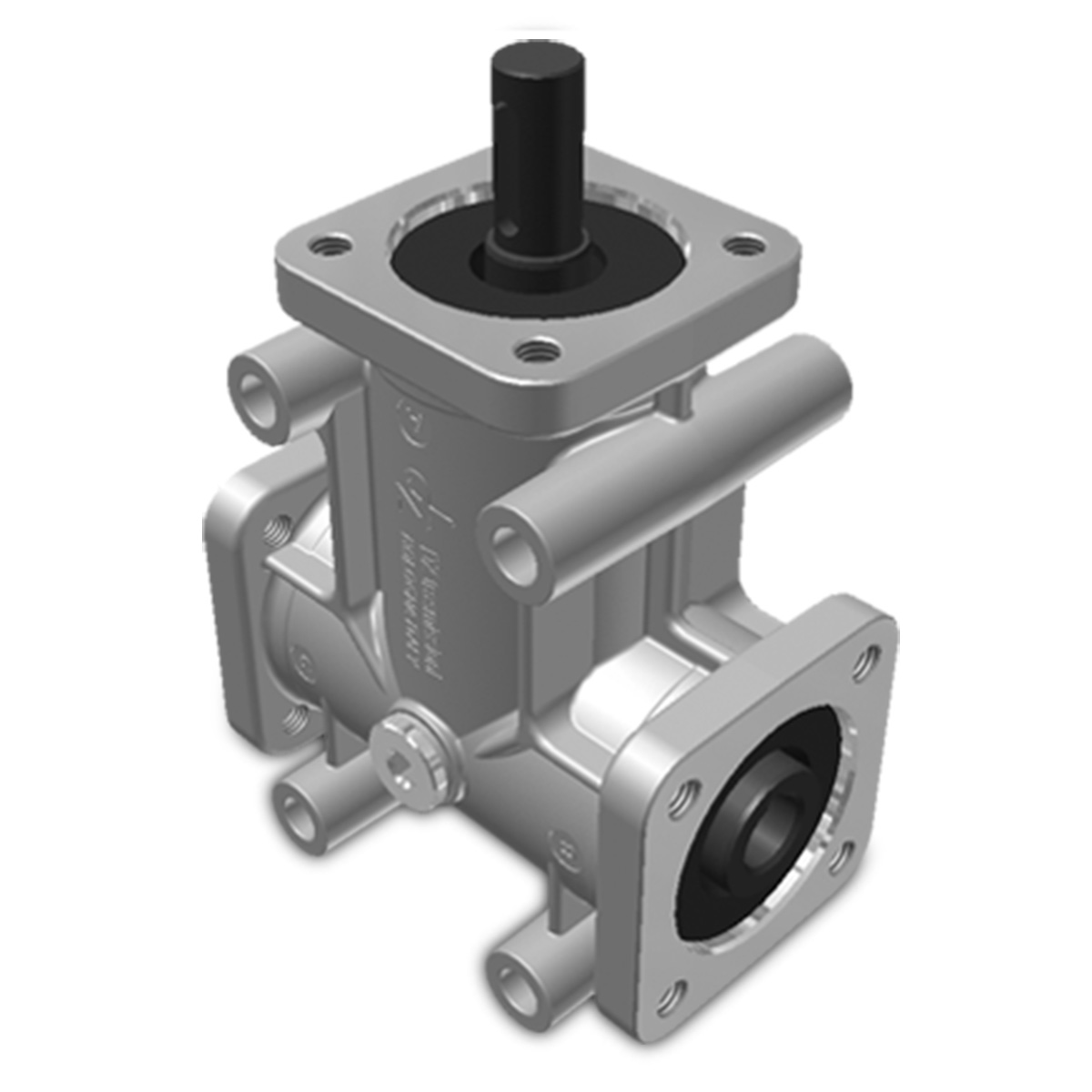
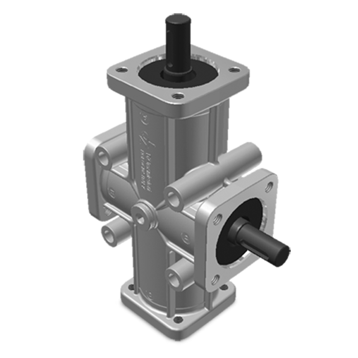
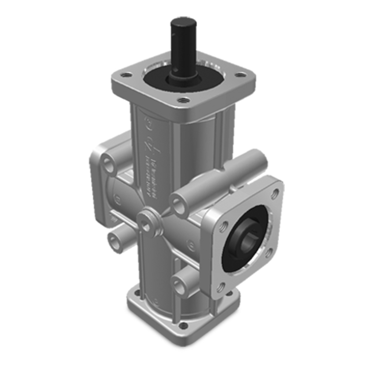
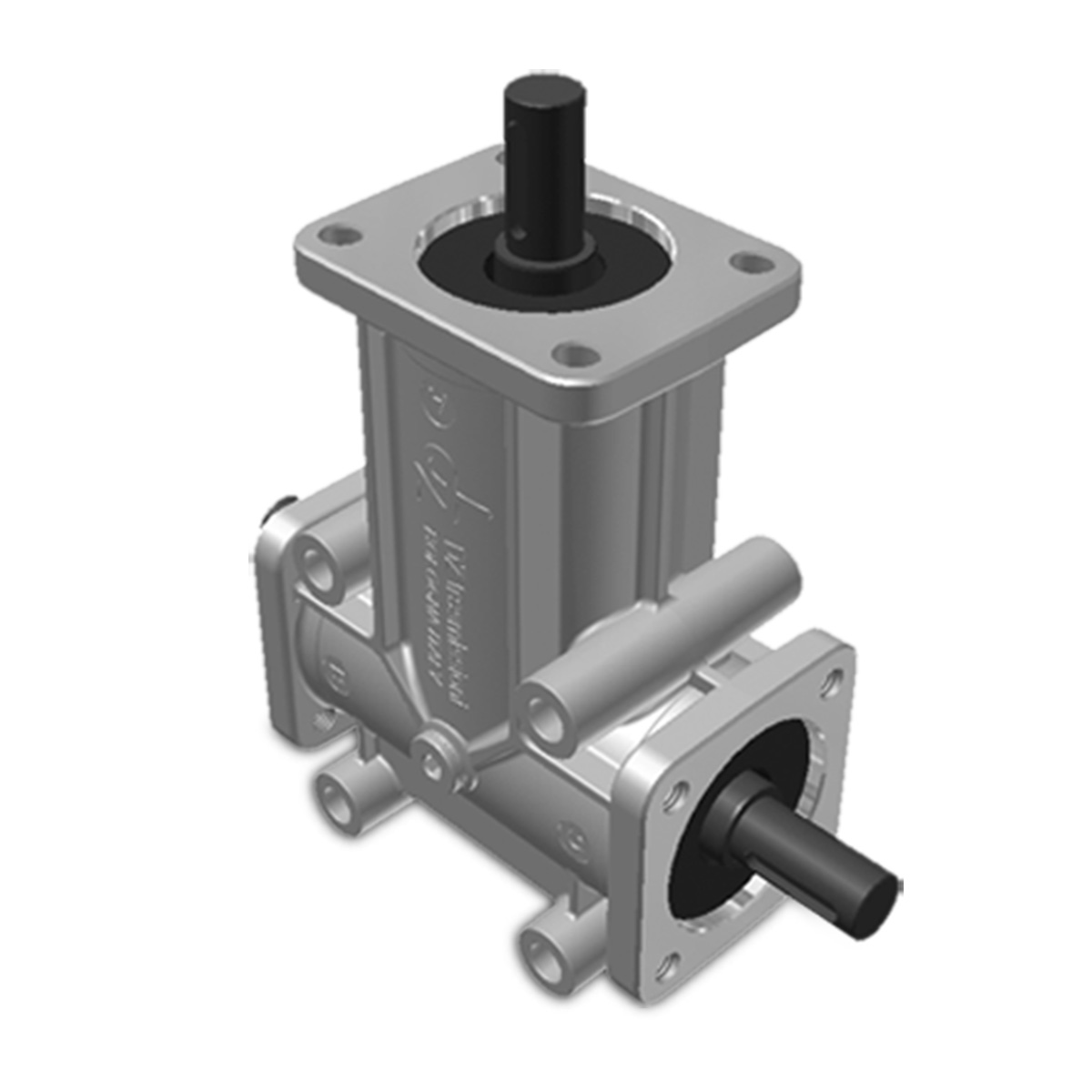
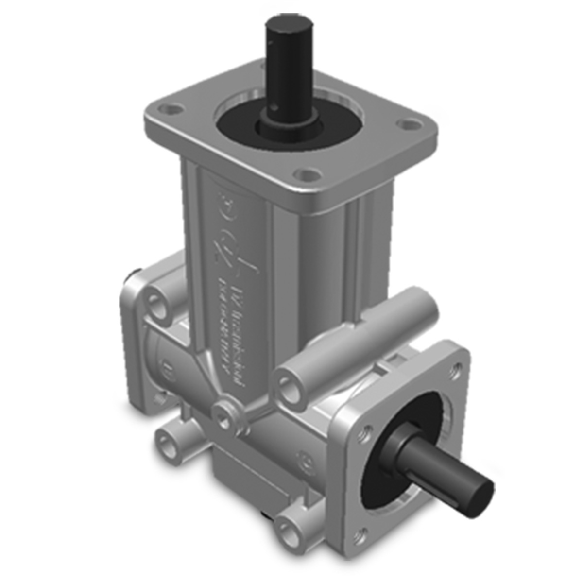
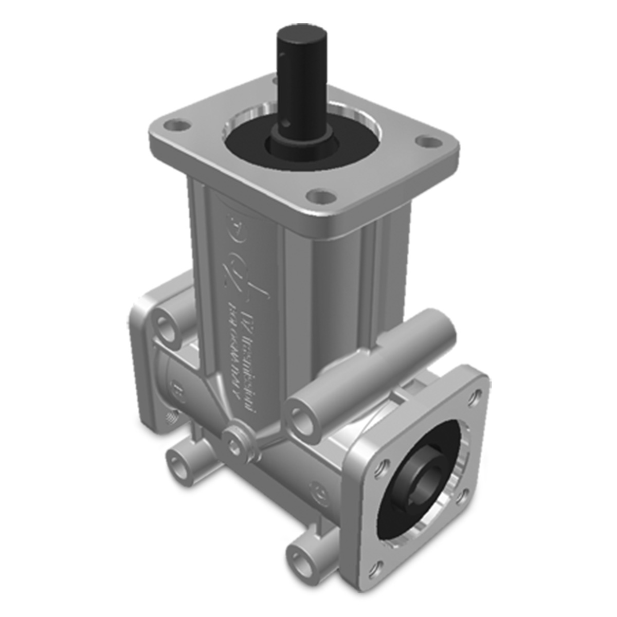
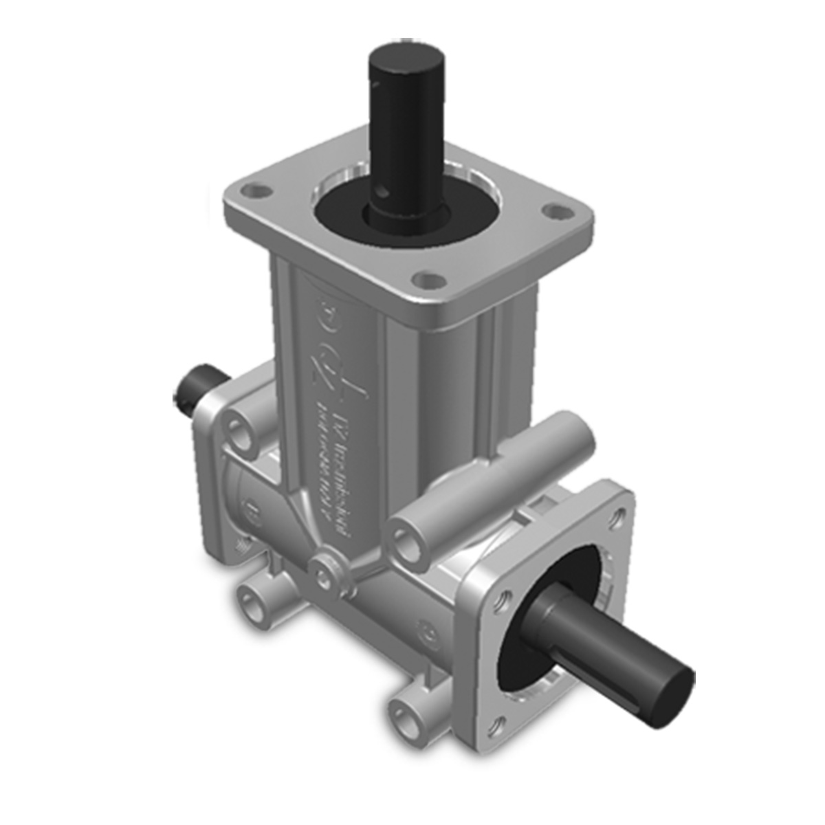
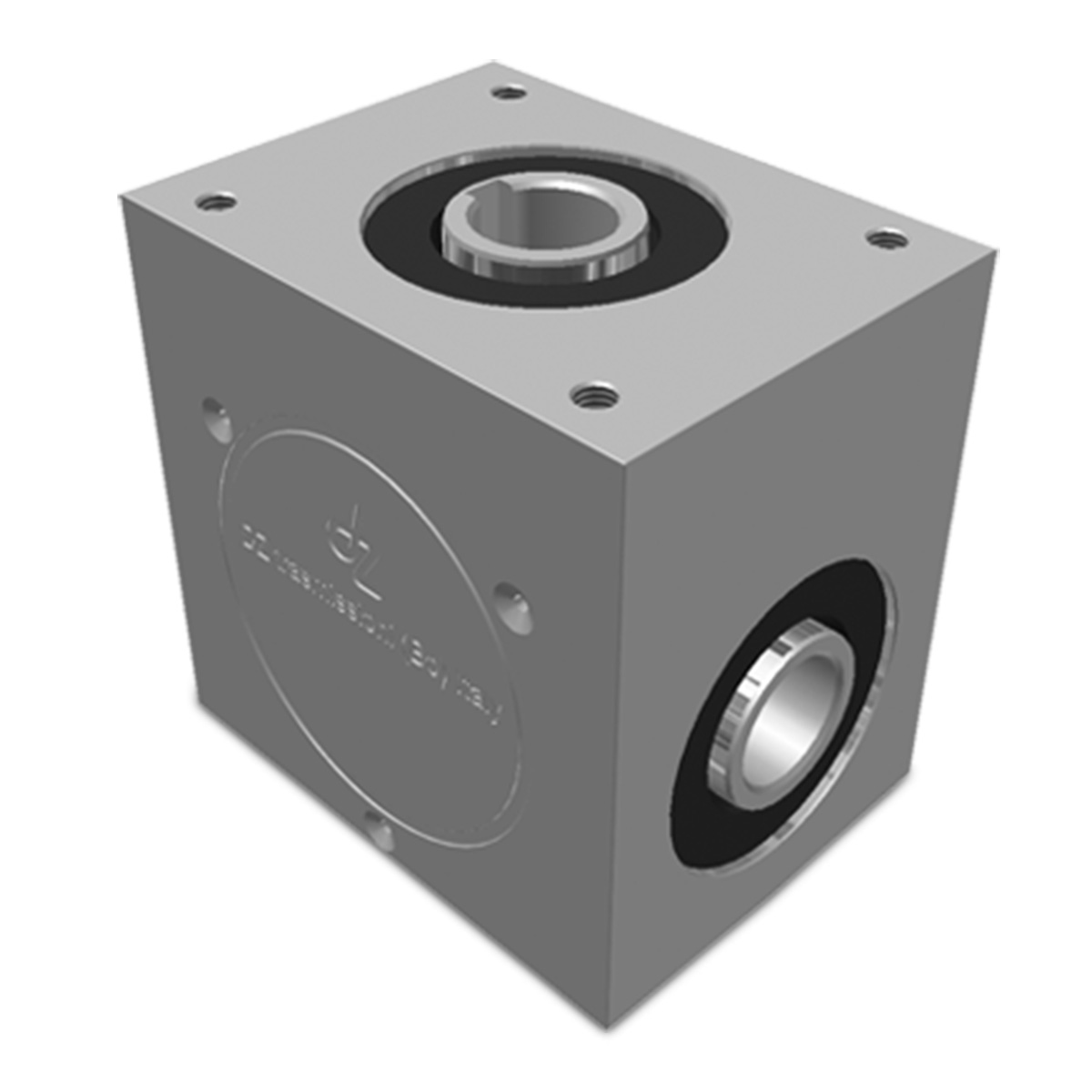
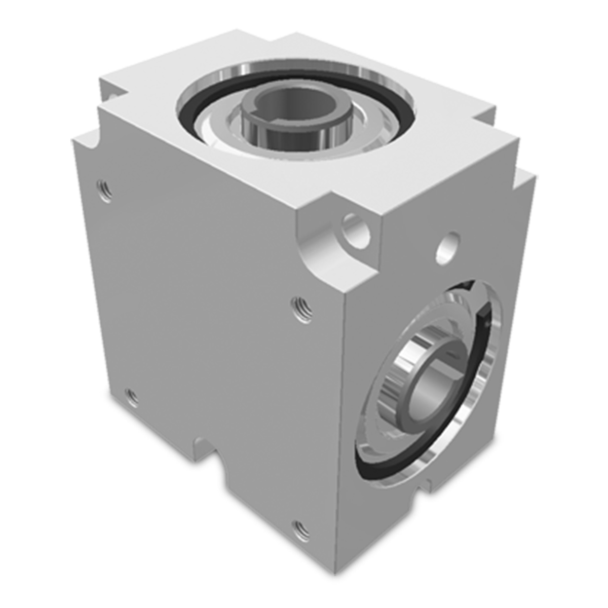
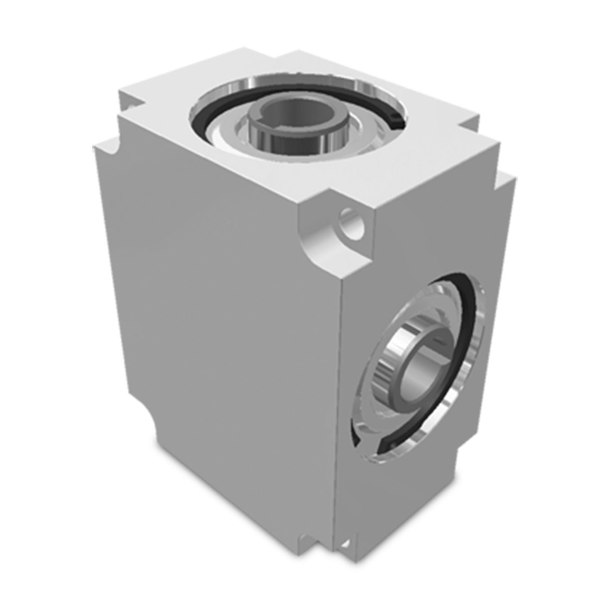
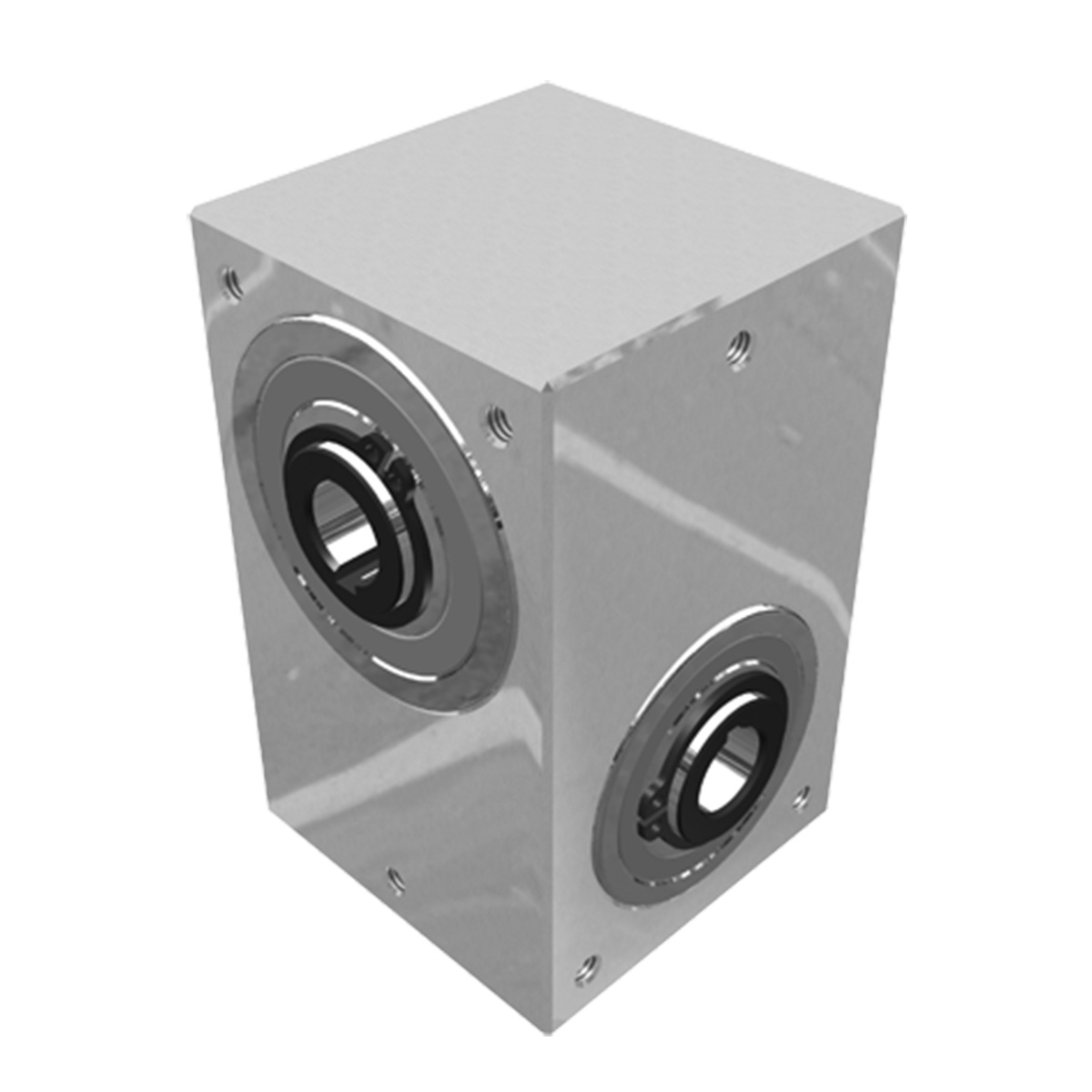
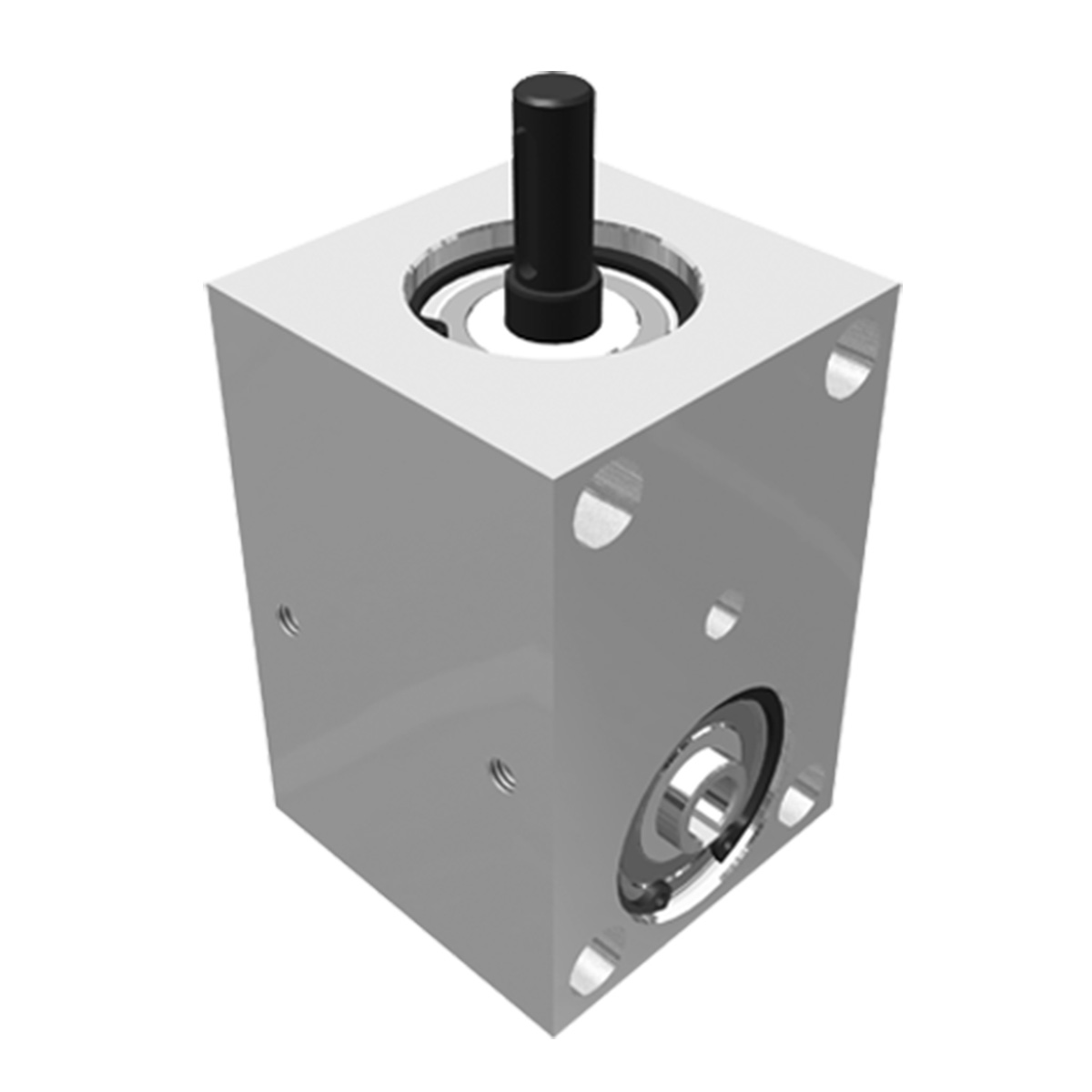
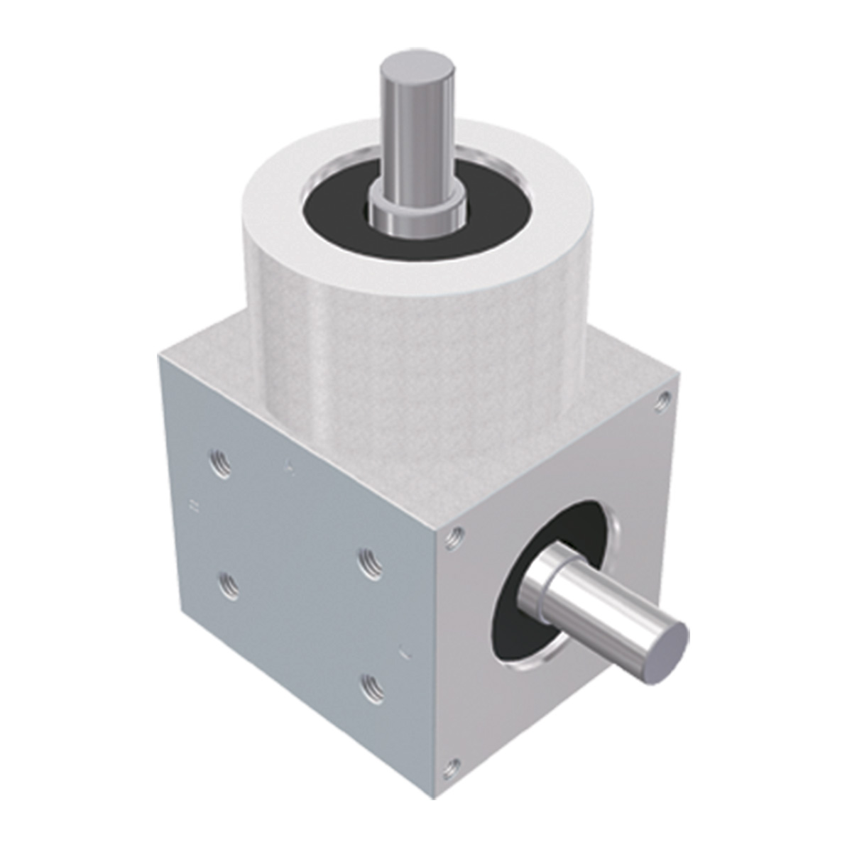
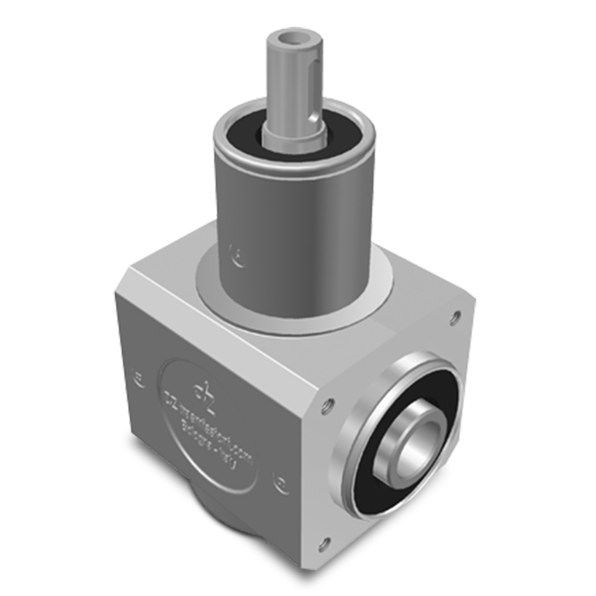
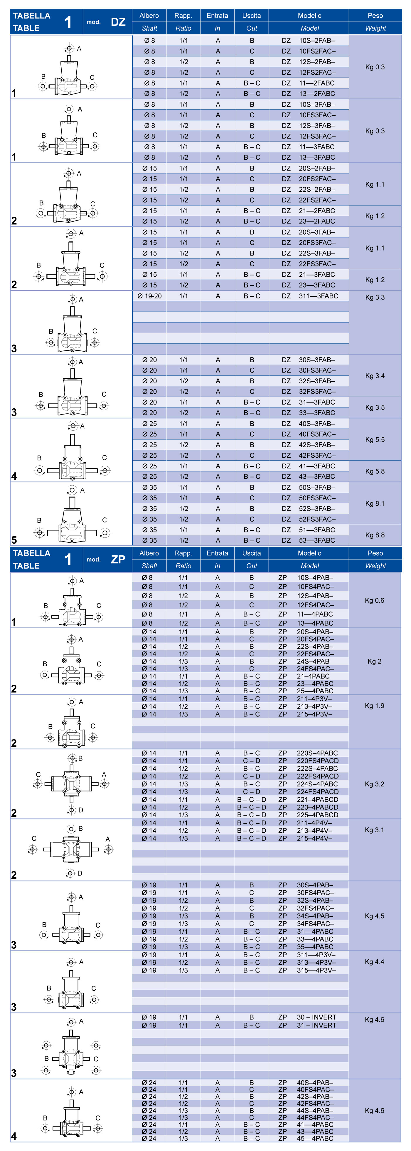
Table 1 shows the following information for each model; the shaft diameter, the transmission ratio, the input shaft A, the output shaft B, C or D and the direction of rotation (front view to the shaft). In accordance with accepted usage, shaft A is the input shaft; on models with a 1:2 and 1:3 ratio, shaft A is the fast shaft.
1
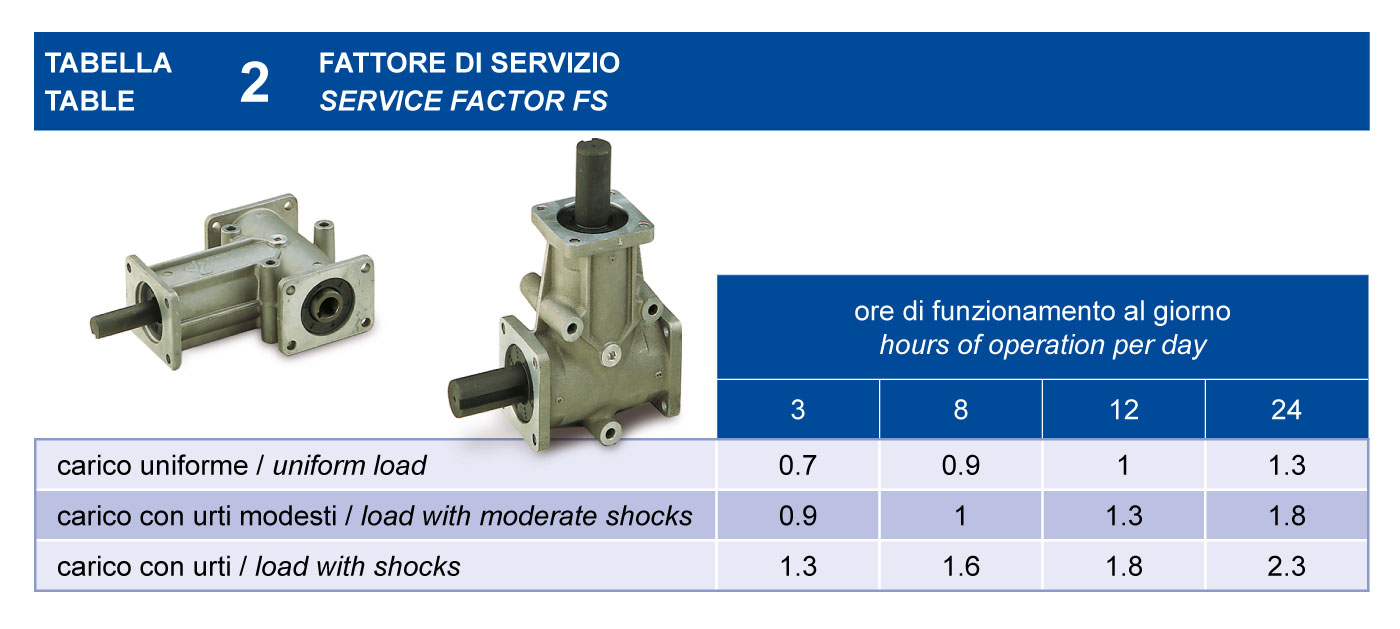
Use Table 2 to define the Service Factor for your application.
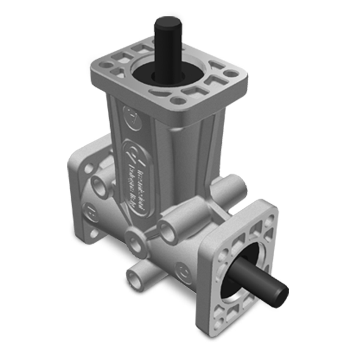
2
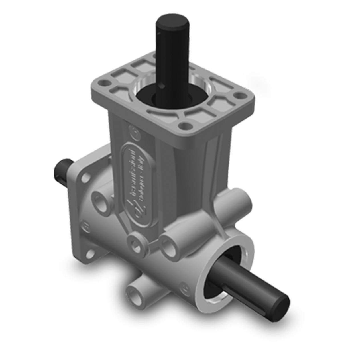
3
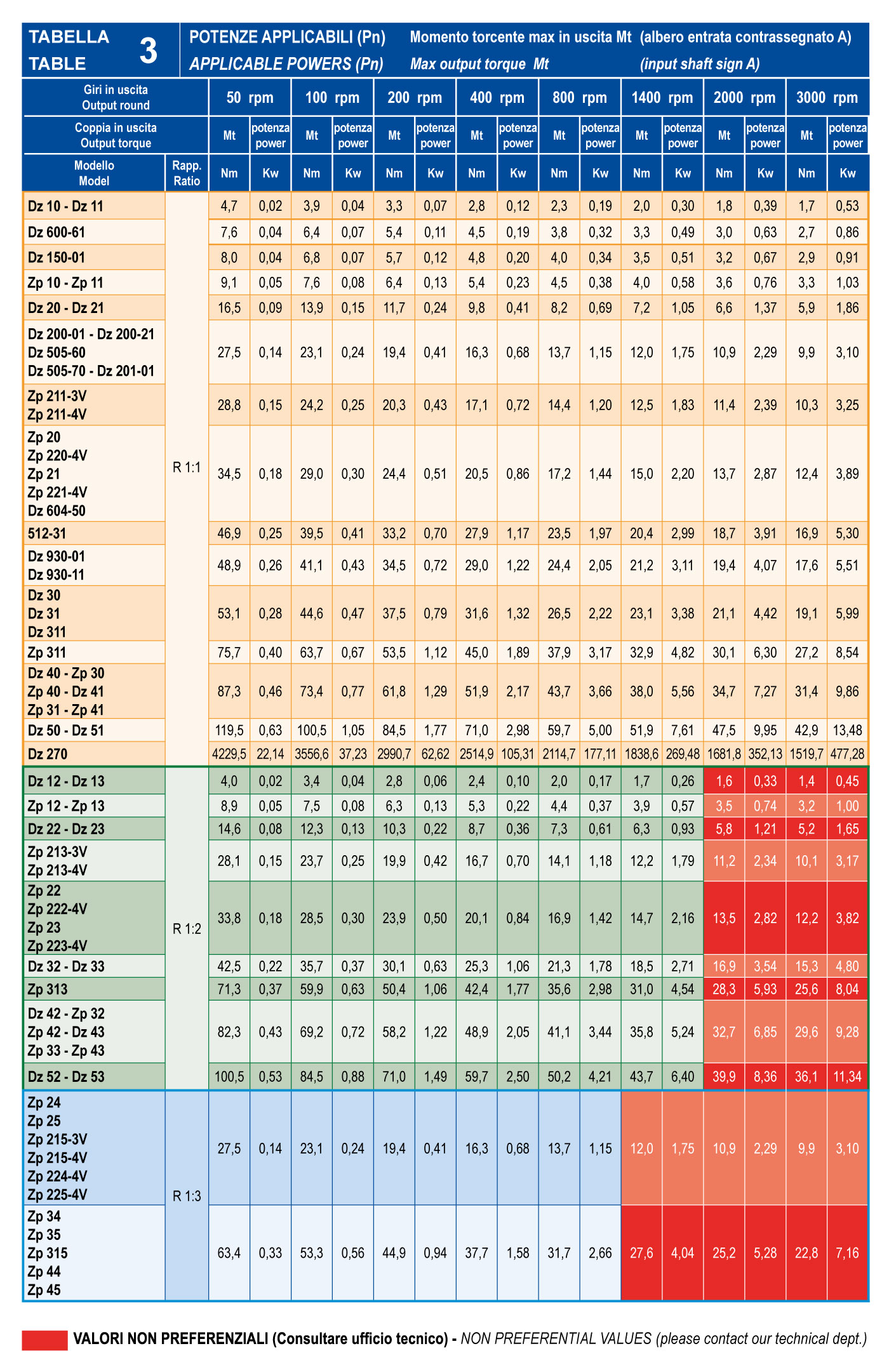
On Table 3, use the output speed and the rated power (Pn) to select the angle gear size and transmission ratio required for your application.
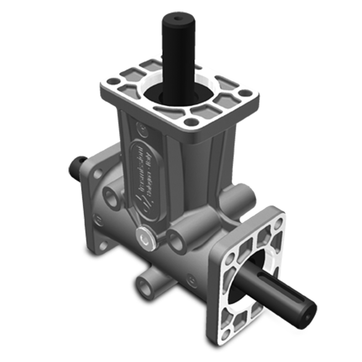
4
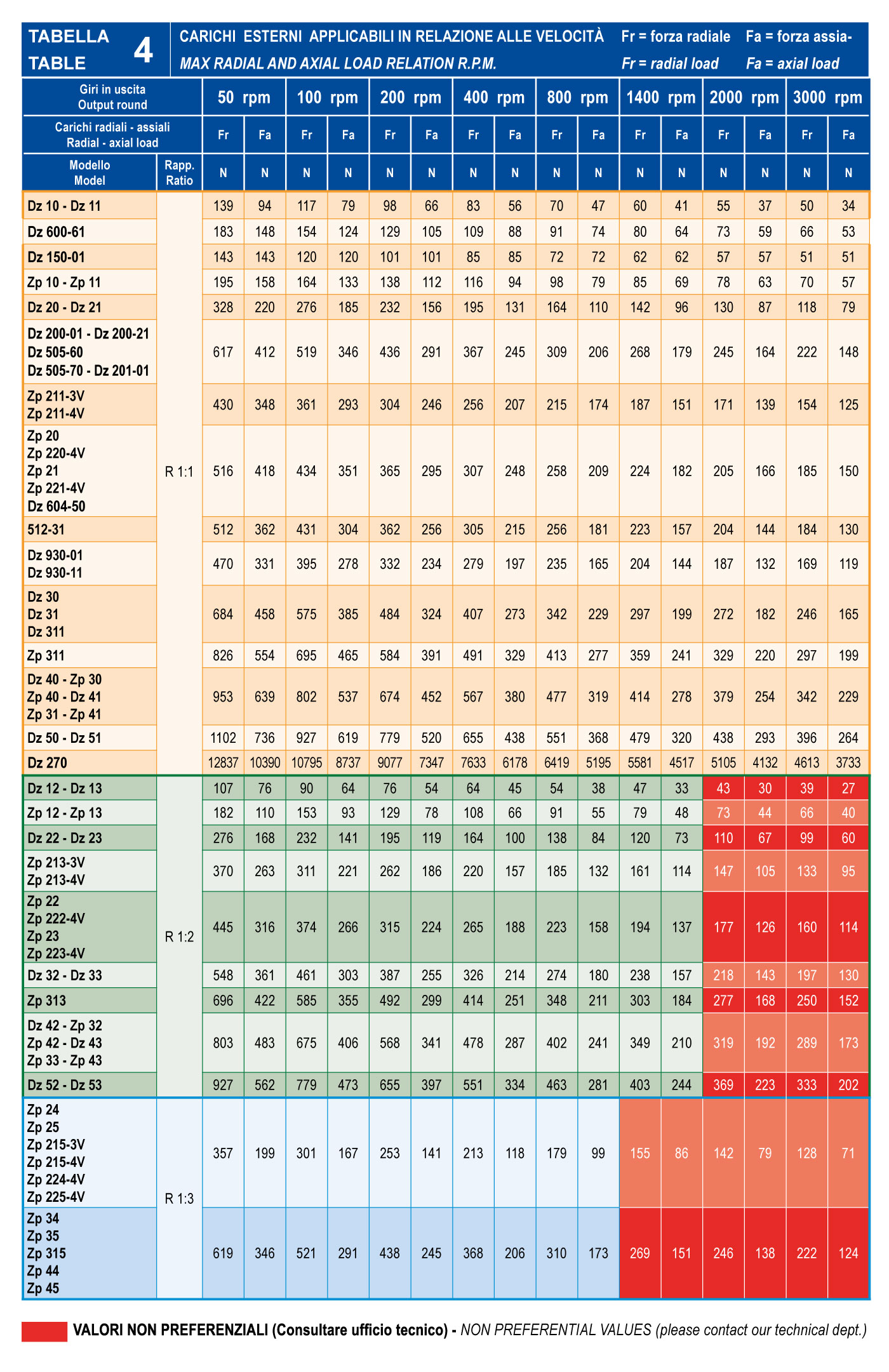
Check that the radial Fr and axial Fa loads applied at the centre of the protusion of every single shaft or at the centre of the hollow shaft does not exeed the values shown in table 4.
5
6
7